Reports Menu
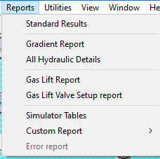
The Reports menu offers the following commands:
| Option | Description |
|---|---|
| Standard Results | Display the basic results and input parameters. |
| Gradient Report | Display a report with pressure, temperature, and other values for a series of depths. |
| All Hydraulic Details | Display detailed hydraulics calculations showing all data in the gradient report plus intermediate PVT and hydraulics-specific results. Velocity values are included. |
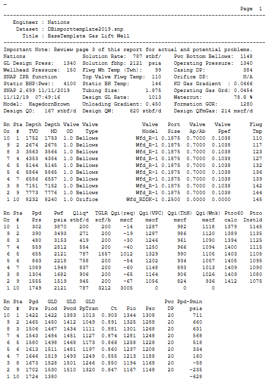
| Gaslift Report | Display the gas-lift design report. |
| Gas Lift Valve/Mandrel Setup Report | Create and open an MS Word setup report as a starting point for formal reports to clients or field personnel. |
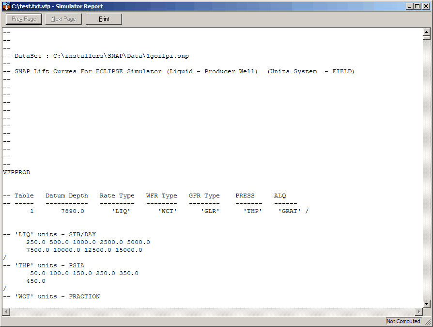
| Simulator Tables | Display simulator table output. |
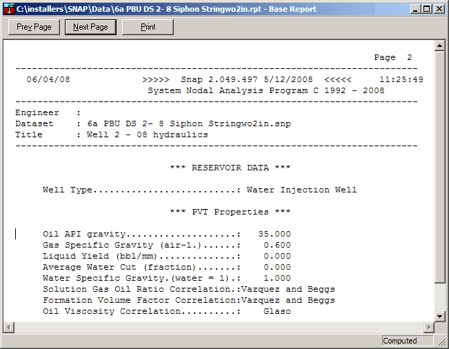
1. Detailed Hydraulics Output
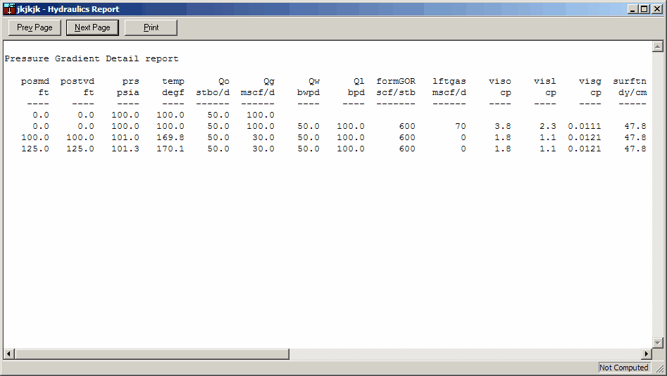
Pressure Gradient Detail report:
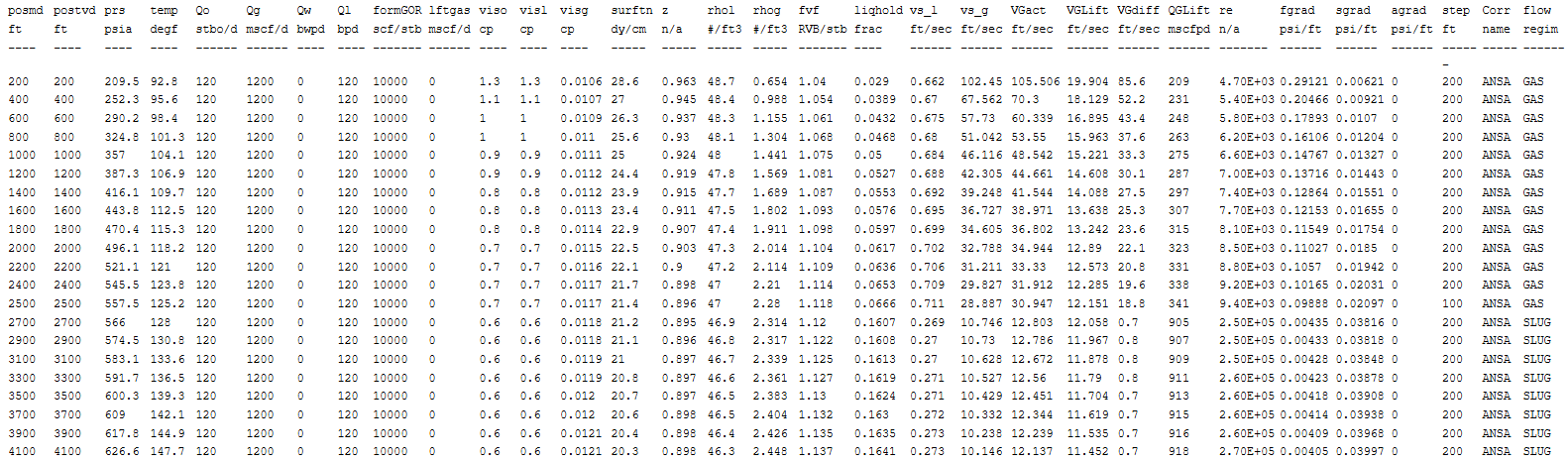
Column Definitions:
| Column | Units | Definition |
|---|---|---|
| posmd | ft | Measured Depth Position in wellbore |
| postvd | ft | True Vertical Depth Position in wellbore |
| prs | psia | Pressure at that point in the wellbore |
| temp | degf | Temperature at that point in the wellbore |
| Qo | stbo/d | Oil rate |
| Qg | mscf/d | Gas rate originating from the beginning of the wellbore |
| Qw | bwpd | Water Rate |
| Ql | bpd | Total Liquid Rate |
| formGOR | scf/stb | Formation GOR |
| lftgas | mscf/d | Lift gas at this wellbore location |
| viso | cp | Oil Viscosity at this temperature and pressure |
| visl | cp | Liquid Viscosity at this temperature and pressure |
| visg | cp | Gas Viscosity at this temperature and pressure |
| surftn | dy/cm | Liquid / gas surface tension |
| z | n/a | Zfactor |
| rhol | #/ft3 | Liquid Density |
| rhog | #/ft3 | Gas Density |
| fvf | RVB/stb | Formation Volume Factor |
| liqhold | frac | Liquid Fraction |
| vs_l | ft/sec | Superficial liquid Velocity |
| vs_g | ft/sec | Superficial gas velocity |
| VGact | ft/sec | Actual In situ gas velocity |
| VGMinL | ft/sec | Actual In situ gas velocity |
| VGdiff | ft/sec | Difference in Lift and actual velocity |
| QGMinL | mscfpd | Gas rate required to unload well at this location |
| re | n/a | Reynold's Number |
| fgrad | psi/ft | Friction Gradient |
| sgrad | psi/ft | Hydrostatic Gradient |
| agrad | psi/ft | Acceleration Gradient |
| step | ft | Iteration step in wellbore |
| Corr | name | Correlation name |
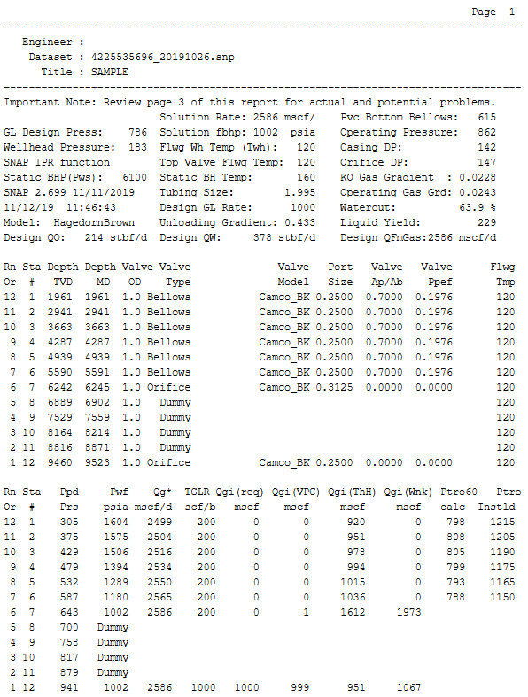
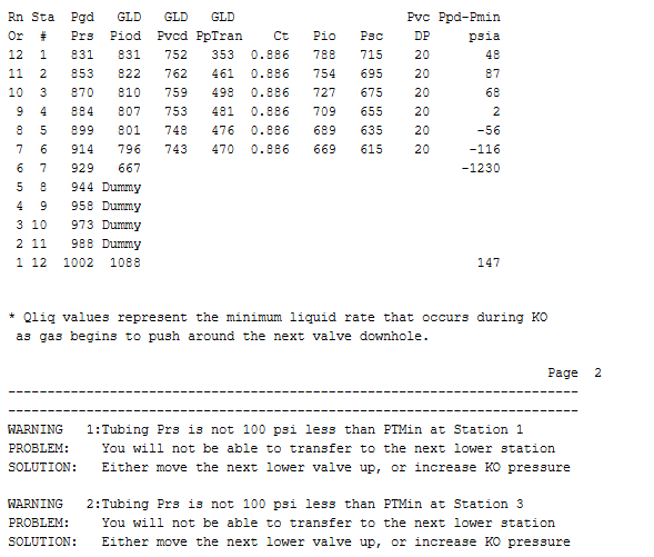
2. GasLift Design Report
3. Simulator Table Output
4. Reports, Navigation Bar
The Report Navigation Bar appears at the top of every report window. It lets you move between pages and print the current report.
Location in the application
Menus > Reports Menu
- Prev Page moves to the previous page of the report.
- Next Page moves to the next page of the report.
- Print opens your system print dialog to print the current report view.
5. Gas Lift Setup Report Detail
Gas Lift Setup reports are formal, field-ready documents that bundle the valve-running details and key design outputs for a specific well.
This 4-page report includes:
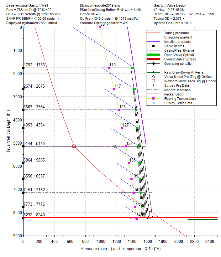
- Design plot
- One-page SNAP design report
- Slickline procedure with the design inputs
- Recommended Unloading procedure that uses well-specific values and values embedded in
GLVSETUPTEMPLATE.RTF.
5.1. Sample report
5.2. Slick Line Procedure
Run the following gas lift design based on the HagedornBrown hydraulic correlation, 788 BLPD, 79% Water Cut, 1013 Mscfd lift gas, 1280 FGOR, kickoff pressure of 1340.0 psi, and Wfd_R-1 valves.
| # | MD (RKB) | Valve OD | Valve Name | Port Size | Surface Open Press | Surface Close Press | TRO Press (60 °F) |
|---|---|---|---|---|---|---|---|
| 1 | 1753 | 1" | Wfd_R-1 | 3/16" | 1344 | 1308 | 1379 |
| 2 | 2675 | 1" | Wfd_R-1 | 3/16" | 1325 | 1288 | 1389 |
| 3 | 3564 | 1" | Wfd_R-1 | 3/16" | 1301 | 1268 | 1394 |
| 4 | 4354 | 1" | Wfd_R-1 | 3/16" | 1281 | 1248 | 1400 |
| 5 | 5145 | 1" | Wfd_R-1 | 3/16" | 1258 | 1228 | 1403 |
| 6 | 5865 | 1" | Wfd_R-1 | 3/16" | 1237 | 1208 | 1405 |
| 7 | 6557 | 1" | Wfd_R-1 | 3/16" | 1213 | 1188 | 1409 |
| 8 | 7152 | 1" | Wfd_R-1 | 3/16" | 1194 | 1168 | 1409 |
| 9 | 7776 | 1" | Wfd_R-1 | 3/16" | 1167 | 1148 | 1412 |
| 10 | 8240 | 1" | Wfd_RDDK-1 | 1/4" | — Orifice — | ||
5.3. Recommended Unloading Procedure
- Slowly open the production choke to reduce tubing pressure toward common line pressure.
- Start lift-gas injection at 50–150 Mscfd.
- Monitor casing annulus pressure and target a 50–100 psi increase every 30 minutes.
- Increase lift-gas injection up to a maximum of 200 Mscfd.
- At 200 Mscfd the estimated time to drop the annulus fluid level to the 1st gas lift valve is 2.8 hrs.
- After unloading to the 1st valve, increase the gas-lift rate to two-thirds of design: (2/3) × 1013 Mscfd = 675 Mscfd.
- The annulus fluid level will pass each unloading valve; lift-gas injection should stabilize at the orifice within 12–18 hours depending on the number of valves.
- Verify annulus casing pressure is below 1248 psig (closing pressure of the bottom valve).
- Increase lift-gas rate to the design rate: 1013 Mscfd.
- Expect stabilized operating annulus casing pressure near 1340 psig.
5.4. GLVSETUPTEMPLATE.RTF file layout
The GLVSETUPTEMPLATE.rtf ASCII text file controls the formatting and fixed text used to build detailed gas-lift setup reports. It is recommended that you:
-
Use a plain text editor that does not inject formatting codes when saving, such as Visual Studio, Notepad with word wrap OFF, or Notepad++.
-
Save a backup copy before making edits because it is easy to corrupt this file.
-
Never edit or save this file in Microsoft Word because Word will change the RTF control words that SNAP depends on.
Sample of RTF control text:
Below is a small excerpt of what the template looks like in a plain text editor. The content is not meant to be human-readable; SNAP parses these control words when generating the final report.
\ltrpar \sectd \ltrsect\linex0\endnhere\sectdefaultcl\sftnbj {\*\pnseclvl1\pnucrm\pnstart1\pnindent720\pnhang {\pntxta .}}{\*\pnseclvl2\pnucltr\pnstart1\pnindent720\pnhang {\pntxta .}}{\*\pnseclvl3\pndec\pnstart1\pnindent720\pnhang {\pntxta .}}

{\*\pnseclvl4\pnlcltr\pnstart1\pnindent720\pnhang {\pntxta )}}{\*\pnseclvl5\pndec\pnstart1\pnindent720\pnhang {\pntxtb (}{\pntxta )}}{\*\pnseclvl6\pnlcltr\pnstart1\pnindent720\pnhang {\pntxtb (}{\pntxta )}}{\*\pnseclvl7\pnlcrm\pnstart1\pnindent720\pnhang

{\pntxtb (}{\pntxta )}}{\*\pnseclvl8\pnlcltr\pnstart1\pnindent720\pnhang {\pntxtb (}{\pntxta )}}{\*\pnseclvl9\pnlcrm\pnstart1\pnindent720\pnhang {\pntxtb (}{\pntxta )}}\pard\plain \ltrpar

\ql \li0\ri0\widctlpar\wrapdefault\aspalpha\aspnum\faauto\adjustright\rin0\lin0\itap0 \rtlch\fcs1 \af0\afs20\alang1025 \ltrch\fcs0 \fs20\lang1033\langfe1033\cgrid\langnp1033\langfenp1033 {\rtlch\fcs1 \af2\afs18 \ltrch\fcs0

\f2\fs18\insrsid1517484\charrsid7815509

\par }\pard \ltrpar\ql \li0\ri-270\widctlpar\tx180\wrapdefault\aspalpha\aspnum\faauto\adjustright\rin-270\lin0\itap0\pararsid7815509 {\rtlch\fcs1 \af2\afs18 \ltrch\fcs0 \f2\fs18\insrsid7815509\charrsid7815509

XXXEngineer

}{\rtlch\fcs1 \ab\af2\afs18 \ltrch\fcs0

\b\f2\fs18\insrsid8395705\charrsid7815509

\par }\pard \ltrpar\ql \li0\ri-270\widctlpar\tx180\wrapdefault\aspalpha\aspnum\faauto\adjustright\rin-270\lin0\itap0\pararsid989102 {\rtlch\fcs1 \ab\af4\afs22 \ltrch\fcs0 \b\f4\fs22\insrsid8395705

\par }{\rtlch\fcs1 \ab\af4\afs22 \ltrch\fcs0 \b\f4\fs22\insrsid7815509

\page

\par
5.4.1. Keyword replacement
SNAP searches for keywords that begin with XXX at the start of a line and replaces them as it builds the report.
Keyword rule
Ensure each XXX... keyword begins in column 1 with no leading spaces or tabs so SNAP can find it. Example: XXXEngineer
5.4.2. Example mapping: final report line vs. RTF source
There are also chunks of text that appear in the rtf template report that ultimately flow through to standard lines of information in the formal report. Below is a sample of the final report outline topic and the rtf text that generates that topic.
\par {\listtext\pard\plain\ltrpar \rtlch\fcs1 \af10 \ltrch\fcs0 \f10\fs22\lang1033\langfe1033\langfenp1033\insrsid7815509\charrsid7815509 \loch\af10\dbch\af0\hich\f10 \'d8\tab}}\pard \ltrpar\ql \fi-360\li1440\ri0\widctlpar

\jclisttab\tx1440\wrapdefault\aspalpha\aspnum\faauto\ls9\ilvl1\adjustright\rin0\lin1440\itap0\pararsid7815509 {\rtlch\fcs1 \af0\afs24 \ltrch\fcs0 \fs22\insrsid7815509\charrsid7815509

For any questions or issues with unloading the well.

\par {\listtext\pard\plain\ltrpar \rtlch\fcs1 \af10 \ltrch\fcs0 \f10\fs22\lang1033\langfe1033\langfenp1033\insrsid7815509\charrsid7815509 \loch\af10\dbch\af0\hich\f10 \'d8\tab}

If the operating annulus casing pressure is 150 psi above or below design.

\par }\pard \ltrpar\ql \li0\ri-270\widctlpar\tx180\wrapdefault\aspalpha\aspnum\faauto\adjustright\rin-270\lin0\itap0\pararsid7815509 {\rtlch\fcs1 \af0\afs24 \ltrch\fcs0 \lang1044\langfe1033\langnp1044\insrsid8917662\charrsid10881772

\par }}
5.4.3. Custom templates
If you are a valve supplier and want setup reports to include your logo and standard language automatically, you can build a custom RTF template that embeds your formatting and boilerplate. You can attempt this yourself or contact the SNAP development team for assistance at support@whitson.com.