Wellbore and Flowline
| Feature | Description |
|---|---|
| Wellbore Segments | See discussion below. |
| Deviation Surveys | Paste survey data into the survey panel. Any panel that uses this data will auto-sync as you edit. |
| Wellbore Restrictions | Enter severe bottlenecks such as junk, scale, pinched pipe, or a designed downhole choke. Normal jewelry should not be modeled because the pressure effect is negligible while the computational cost is not. |
| Correlation Advisor | Suggests an appropriate hydraulics model for your case. See the correlations topic for details. |
| Standard Pipe Sizes | Quick reference tables for common tubing and casing OD/ID dimensions. |
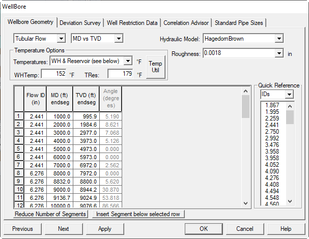
What you edit on the Wellbore Geometry panel:
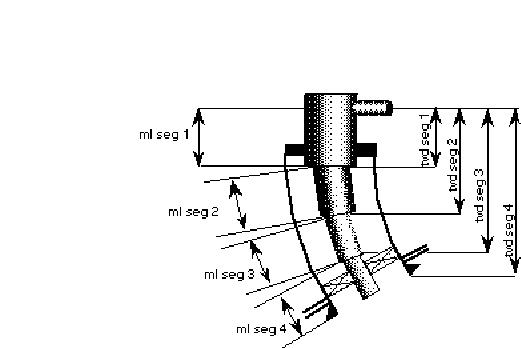
The wellbore geometry is entered as individual segments that describe the well from the wellhead to TD.
Well Geometry options
- Measured Depth vs. True Vertical Depth
- Measured Depth vs. Angle
- True Vertical Depth vs. Angle
Deviation Survey tab: Provide survey stations in the survey panel; geometry displays update with your entries.
Flow Area options
- Tubular Flow (select Tubing ID): flow through the tubing.
- Annular Flow (select Tubing OD and Casing ID): flow through the annulus.
Tubing Inside Diameter (in): Tubing ID. Use the dimensions button to open standard OD/ID tables.
Tubing Outside Diameter (in): Tubing OD.
Casing Inside Diameter (in): Casing ID. Needed only for Annular Flow. Ignore for normal tubular flow.
Measured Depth (ft): Cumulative length along the well path from the wellhead. Also called wireline or driller’s depth. MD affects friction pressure.
True Vertical Depth (ft): Net vertical distance below the wellhead from gyro surveys. TVD affects hydrostatic pressure.
Angle (degrees): Deviation from vertical. Example: a KOP at 2000 ft with 2 deg/100 ft build to 2200 ft MD is entered as 2000 @ 0°, 2100 @ 2°, 2200 @ 4°, etc.
Segment Temperature (°F): Temperature at the end of each segment. The program interpolates linearly between wellhead and bottomhole temperatures, but you can specify a non-linear profile by adding segments with explicit temperatures.
Tubing Roughness (in): Absolute roughness of the pipe segment, used in the friction-factor calculation. The Crane handbook (TP-410) is a good source. See Recommended Values.
1. Hydraulics Correlation Advisor
What this panel does
This selector chooses the multiphase hydraulics correlation used to compute tubing and flowline pressure-rate curves.
1.1. Vertical correlations
Hagedorn & Brown
Developed from a 1,500 ft vertical test well with 1.0–1.5 in tubing, covering wide ranges of liquid rate, GLR, and viscosity. Uses dimensionless groups throughout.
Ref: Hagedorn, A. R., Brown, K. E., JPT, Apr 1965.
Orkiszewski
Predicts 2-phase pressure drop in vertical pipe across bubble, slug, annular-slug transition, and annular-mist regimes. Accuracy within about 10 percent against 148 measured drops. Holdup is derived from observed flow physics and adjusted for deviation angle.
Ref: Orkiszewski, J., JPT, Jun 1967.
Duns & Ros
Vertical flow of gas-liquid mixtures with three regions: I) bubble/plug/part of froth, II) froth remainder and slug, III) mist. Each region has its own holdup correlation, based on extensive air-oil experiments.
Ref: Duns, H., Ros, N. C. J., 6th World Petroleum Congress, 1963.
Aziz (Govier–Aziz–Fogarasi)
Built from 102 field gas-condensate wells over very high GLR. Mechanistic approach with separate momentum equations for core and film, and flash calcs for phase behavior. Benchmarked to field data and empirical methods.
Ref: Aziz, K., Govier, G. W., Forgarasi, M., J. Cdn. Pet. Tech., Jul–Sep 1972.
Beggs & Brill
Original: flow regime is mapped as horizontal first, then horizontal holdup is corrected for inclination. Tests used twin 90 ft acrylic lines for up/down inclination to 90 degrees.
Revised: adds froth flow (no-slip holdup) and uses a single-phase friction factor based on average velocity.
Ref: Beggs, H. D., Brill, J. P., JPT, May 1973.
Mukherjee & Brill
Inclined two-phase flow. Uses Moody no-slip f for bubble/slug friction losses, momentum balance for downhill stratified, and a holdup-based friction factor for annular-mist. Validated with Prudhoe Bay and North Sea data.
Ref: Mukherjee, H., PhD Thesis, Univ. of Tulsa, 1979.
Gray
API-recommended for vertical gas wells (SSSV sizing, API 14B). Liquid holdup correlated with two dimensionless numbers and no-slip holdup.
- Liquid/gas ratio
- Water/gas ratio
In practice it often performs well outside these ranges.
Ref: Gray, H. E., API 14-B SSSV program user manual.
Modified Gray
As above, see Gray.
DunsRosGray
Hybrid that combines Duns & Ros with Gray.
Stoisits
Mechanistic model predating Ansari, retained for posterity.
Author: Rich Stoisits (ARCO).
Cullender & Smith
Use for gas-only systems.
Water Only
Single-phase water with Moody friction factor. No gas.
Ansari
TUFFP mechanistic model predicting patterns and pressure drop for bubble, slug, and annular flows. Evaluated on 1,775 wells, including 371 from Prudhoe Bay.
TUFFP program results.
OLGA Steady State (Olgas)
Based largely on SINTEF’s 800 m, 8 in loop (20–90 barg; gas U_s up to 13 m/s; liquid U_s up to 4 m/s; various liquids; nitrogen gas). Considers stratified, annular, slug, and dispersed bubble, with minimum-slip criteria for transitions. Over 10,000 experiments. Steady and transient facility, but here steady-state.
Chokshi
Flow-pattern-free statistical correlation for vertical two-phase liquid holdup and pressure gradient in large-diameter tubing. English units.
Ref: Chokshi, R. N., PhD, Univ. of Tulsa, 1994; code rev. Aug 1994.
1.2. Horizontal correlations
Dukler
Widely used for small and large diameters. No explicit inclination term but often combined with Flanigan for hilly terrain.
Ref: AGA-API Project NX-28, May 1969.
Beggs & Brill
Original and Revised, as described above for vertical; applied to horizontal and inclined pipes as well.
Mukherjee & Brill
As above; includes inclined behavior.
Dukler & Eaton
Two 1,700 ft lines (2 in and 4 in), broad ranges in rates, viscosity, and pressure. Holdup and friction factor via regression on dimensionless groups. Note: friction factor does not degenerate to single-phase limits; use within valid abscissa range about 1e4 to 1e6.
See also Dukler.
Minami–Beggs–Brill
Additional updates to B&B.
1.3. Other non-SNAP correlations
NoSlip
Homogeneous model with no phase slippage. Properties are mixture-averaged; friction factor from single-phase Moody correlation.
BJA for Condensates
Baker Jardine & Associates model for gas-condensate lines with no-slip liquid volume fraction < 0.1. Uses Taitel–Dukler map, modified momentum balances, and field-tested updates to interfacial shear due to liquid surface roughness.
AGA & Flanigan
For horizontal and inclined gas-condensate gathering systems. Uses Taitel–Dukler regimes, Dukler frictional loss and holdup, and Flanigan elevational pressure change.
Oliemans
Developed from large-diameter condensate pipelines. Uses Taitel–Dukler for regime prediction and a pressure-drop model that honors the single-phase limits. Based on limited data from a 30 in, 100 km pipeline at ~100 barg.
2. Wellbore Deviation Surveys
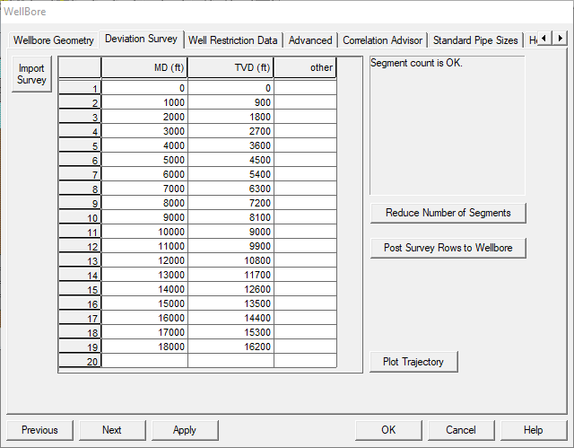
Fast entry
You can paste deviation-survey rows directly from your deviation records. If you do not have those records, it is usually faster to enter a few MD/TVD pairs in the Wellbore and Gas-lift panels instead of hand-typing long surveys.
-
What the survey drives: Once a Deviation Survey is loaded, SNAP will automatically synchronize any panel that needs MD/TVD pairs, including wellbore, gas-lift, and jet-pump inputs.
-
Keep surveys lean: Hundreds of points make files larger without adding useful resolution. Use Reduce Number of Segments until the count is under ~20. The reducer keeps the most meaningful trajectory changes.
-
Turn off auto-sync: To lock down values and stop synchronization, remove the deviation-survey rows and save the dataset.
3. Wellbore Restrictions
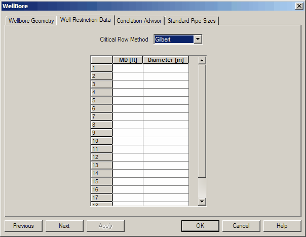
Use this panel to model only severe bottlenecks such as junk in tubing, severe scale, pinched pipe, or a designed downhole choke. Minor hardware like nipples, SSSVs, and other typical tubing jewelry should be ignored because their producing-condition pressure drop is negligible and adds unnecessary uncertainty.
Only model real bottlenecks
This feature is for major restrictions that materially affect system hydraulics. Avoid adding routine fittings that will not change the tubing curve in a meaningful way.
Fields
-
Restriction I.D. (in):
Inner diameter used to compute two-phase pressure drop across a sharp-edged orifice. The drop is treated as a shock, so no length term is used.- If flow is critical, one of the critical-flow correlations is applied (Gilbert is recommended).
- If flow is subcritical, a multiphase subcritical correlation is used.
-
For wellbore restrictions
Measured distance from wellhead (ft): distance from the restriction up to the wellhead. -
For flowline restrictions
Measured distance from separator (ft): distance from the restriction back to the separator.
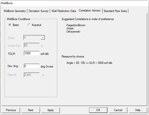
4. Wellbore Correlation Advisor
Use this panel to review and choose hydraulic relationships for tubing and flowline calculations. Correlations often perform best within the conditions they were built for, and can perform poorly outside those ranges. This screen helps you narrow to a sensible short list for your case.
Where to start
- Mostly vertical wells at moderate rates: try Hagedorn & Brown or Orkiszewski.
- Inclined or horizontal sections: try Beggs & Brill (revised) or Mukherjee & Brill.
- High-rate gas or gas-condensate: consider Aziz, Gray/Modified Gray, DunsRosGray, or Ansari.
- Large lines and gathering systems: consider Dukler, AGA & Flanigan, OLGA Steady State, or Oliemans.
Workflow:
- Open the advisor and preselect 2–4 candidates that match your geometry, fluids, and rate range.
- Generate tubing/flowline curves and compare to measured gradients or reliable test points.
- Keep the best 1–2 correlations and iterate on sensitivities as needed.
5. Heat Transfer and Heat Balance Properties
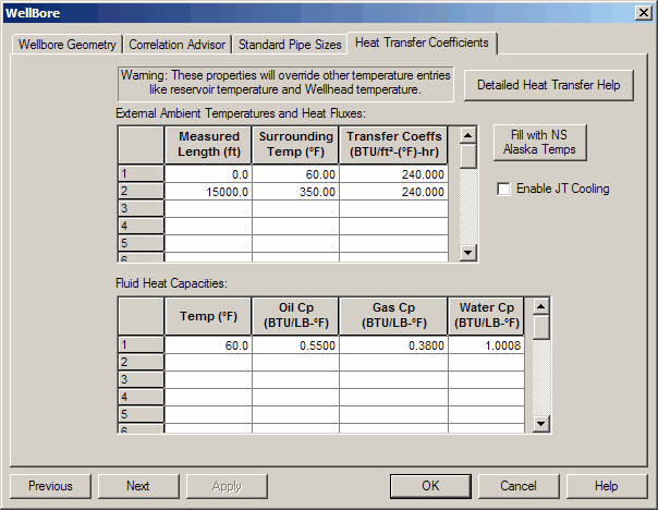
Access path
- Open Wellbore.
- Under Temperature Options, choose Rigorous Heat Transfer.
- Click Heat Transfer Coefficients.
This panel summarizes the ScandPower/Amoco HeatTransfer.xls logic used to:
- compute outside film coefficients for OLGA,
- compute the equivalent conduction of a well annulus,
- compute inside film coefficients for forced convection in a pipe.
Sheets included in the spreadsheet:
a) Forced convection for water past a pipeline
b) Forced convection for air past a pipeline
c) Free convection for water
d) Free convection for air
e) General forced convection calculations
f) General free convection calculations
g) Well annulus equivalent conduction
h) Forced convection inside a pipe
Data and units
- Sheets a–d have built-in property correlations for water and air.
- The two general sheets require user-supplied properties.
- Only the input cells on a–d are editable; other cells are protected (no password).
- Inputs can be in English or Metric units. There is no cross-conversion inside the sheet.
- In the UI, input items are shown in red.
5.1. Outside convection correlations (pipes)
Forced convection:
Free convection
5.2. Well annulus heat transfer
OLGA computes inside-film convection and heat loss to surroundings; remaining heat transfer is treated as conduction.
For wells with annular convection, convert the convective film coefficients in the annulus into an equivalent thermal conductivity of the annular fluid. The sheet provides this conversion and returns an effective .
5.3. Forced convection inside a pipe
Laminar flow:
Turbulent flow:
Transition flow: .
Assume varies linearly from the laminar value in Eq. 4/Eq. 5 to the turbulent value in Eq. 6.
Mixture properties
For two-phase calculations, properties are volumetric averages except , which is averaged by mass flux of each phase. Compute and from the mixture properties.
5.4. Example inputs and results
| Property | English | Metric |
|---|---|---|
| Superficial Gas Velocity | 1.00 ft/s | 0 m/s |
| Superficial Liquid Velocity | 1.00 ft/s | 0.305 m/s |
| Gas Density | 5.00 lbm/ft³ | 80.10 kg/m³ |
| Liquid Density | 62.40 lbm/ft³ | 1000.00 kg/m³ |
| Gas Viscosity | 0.015 cP | 0.000015 kg/m/s |
| Liquid Viscosity | 400.00 cP | 0.400000 kg/m/s |
| Gas Specific Heat | 0.60 BTU/lbm/°F | 2510.0 J/kg/°C |
| Liquid Specific Heat | 1.00 BTU/lbm/°F | 4180.0 J/kg/°C |
| Gas Thermal Conductivity | 0.031 BTU/hr/ft/°F | 0.0536 W/m/°C |
| Liquid Thermal Conductivity | 0.083 BTU/hr/ft/°F | 0.144 W/m/°C |
| Diameter | 12.000 inch | 0.305 m |
| Length (laminar only) | 11.000 mile | 16.000 km |
| Mixture Properties | ||
| Velocity | 2.00 ft/s | 0.31 m/s |
| Density | 33.70 lbm/ft³ | 1000.00 kg/m³ |
| Viscosity | 200.01 cP | 0.400000 kg/m/s |
| Specific Heat | 0.97 BTU/lbm/°F | 4180.0 J/kg/°C |
| Thermal Conductivity | 0.057 BTU/hr/ft/°F | 0.1440 W/m/°C |
| Re | 501 | 233 |
| Pr | 8237.38 | 11611.11 |
| Nu | 7.60 | 6.83 |
| h | 0.43 BTU/hr/ft²/°F | 3.22 W/m²/°C |
6. Standard pipe sizes
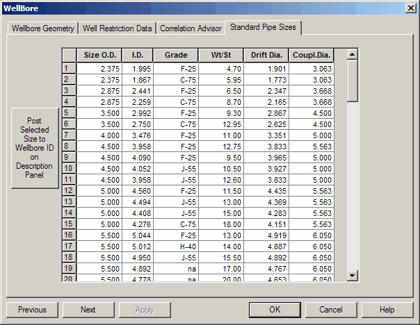
Access path: Wellbore → Standard Pipe Sizes
7. Flowline
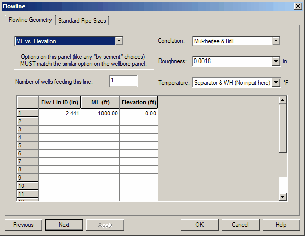
The Flowline Geometry panel lets you describe the full flowline using segments to capture profile, diameter changes, and nonlinear temperature profiles. Geometry is entered from the separator toward the wellhead.
Segment limit
The total number of segments across flowline + wellbore must be ≤ 20.
Flowline geometry options:
- Measured length vs. elevation
- Measured length vs. angle
- Elevation vs. angle
Field definitions:
- Flowline inside diameter (in): Inside diameter of the flowline.
- Flowline measured length (ft): Cumulative measured pipe length from the separator.
Example: a 100-ft section attached to a 1,500-ft section (at the separator) gives 1,600 ft cumulative length. - Flowline elevation (ft): Cumulative net elevation relative to the separator inlet (positive downward, same sign convention as the wellbore).
If the separator is uphill from the wellhead, the final segment elevation should be positive. - Flowline angle (degrees): Angle measured clockwise from horizontal, looking from the separator to the wellhead.
Horizontal = 0. Positive if the separator is uphill. Angles are not cumulative. - Segment temperature (°F): Temperature at the end of each segment.
The program uses wellhead and separator temperatures to apply a linear gradient by default. Enter additional segments and temperatures to impose a nonlinear profile. - Flowline roughness (in): Absolute roughness used to compute the friction factor.
The Crane Handbook (TP-410) is a common source.
8. Advanced hydraulics options
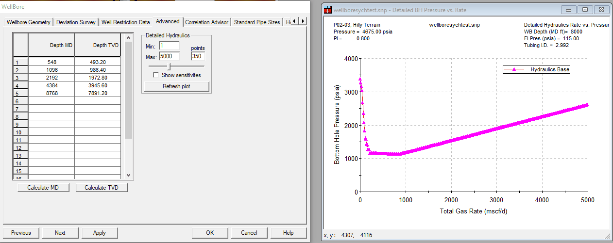
The above items are located on the Advanced panel.