General Description
1. General Description
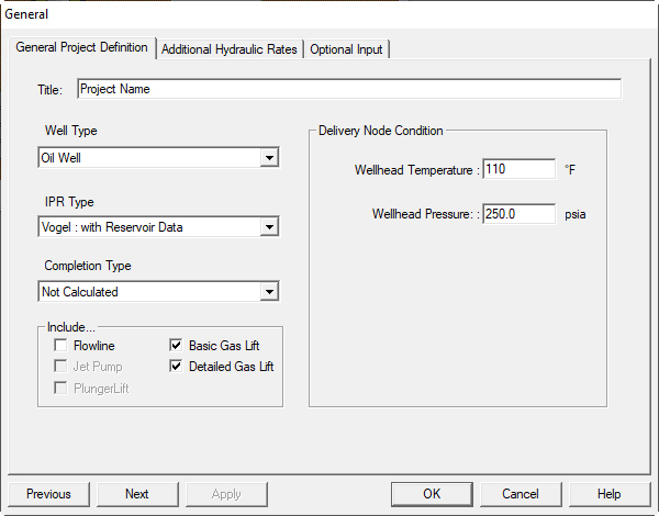
The following items can be edited on the General Information panel:
-
Title: Identifies the well or field. Maximum of 60 characters. Appears at the top of each page of the output report. All characters, numbers and symbols are allowed.
-
Oil Well: IPR is generated in stock tank barrels of liquid per day, and multiphase flow correlations are used for pressure drop in the flowline and tubing.
-
Gas Well: IPR is generated using gas properties in mscfd, and single or multiphase correlations are used for pressure drop in the flowline and tubing.
-
Completion Type: Provides options for including pressure drops in completions. Set to Not Calculated unless you have detailed completion data or are doing a completion study.
-
Include Flowline: When checked, the analysis includes the flowline, the tubing, and the reservoir. The total system includes the separator, flowline, wellhead, tubing, bottomhole completion, and reservoir.
-
Gas Lifted: See "Artificial Lift Options". The well is lifted using gas injection. Specify gas injection pressure and temperature, injection point, and injected gas volume. The program uses the formation gas–liquid ratio from the reservoir to the injection point and the total gas–liquid ratio from the injection point to the terminal point (wellhead or separator).
-
Wellhead Temperature (F): Stabilized flowing wellhead temperature. Used with separator temperature to compute a linear temperature profile in the flowline, and with bottomhole temperature to compute the well temperature profile.
-
Wellhead Pressure (psia): Starting pressure for wellbore and tubing hydraulic performance curves.
Valid only when Include Flowline is unchecked
Use Wellhead Pressure only if Include Flowline is not selected.
-
Flowline Pressure (psia): Starting pressure for flowline and tubing hydraulic performance curves.
Valid only when Include Flowline is checked
Use Flowline Pressure only if Include Flowline is selected.
-
Flowline Temperature (F): Starting temperature for flowline and tubing hydraulic performance curves.
Valid only when Include Flowline is checked
Use Flowline Temperature only if Include Flowline is selected.
-
Optional Hydraulics Flow Rates: Allows entries for Oil, Gas, Water, and Total Liquid rates. See 3. Additional Hydraulics Flow Rates.
-
Optional Input: Entry area for Engineer Name, API number, Hydraulics Detail file location, and Formal Gas Lift Report defaults. See 2. Optional Input.
Toolbar: ![]()
Keys: Alt-I-G
2. Optional Input
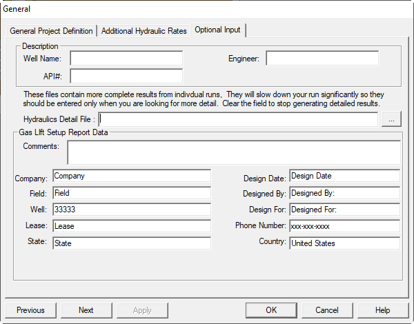
The following items can be edited:
- Well Name
- API #
- Engineer
- Hydraulics Detail File location
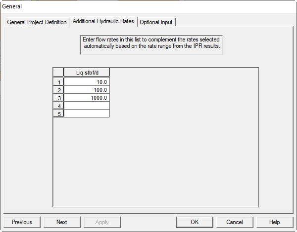
3. Additional Hydraulics Flow Rates
This dialog allows you to identify specific flow rates at which the hydraulics curve will be evaluated. Hydraulics calculations can be time consuming, so start with a modest number of rates for screening. After you find the general solution, evaluate discrete points around the intersection to improve accuracy.
- FLOW RATE (stbpd or mscfd): Table of rates for constructing the flowline and/or tubing hydraulics curve. Rates are sorted internally; they do not need to be in ascending order.
Items that can be edited on the Additional Hydraulics panel are:
- Oil Rate
- Water Rate
4. Well Types
4.1. Oil Wells
Oil well IPR calculations focus on the flowing liquid phase and can take many forms. Most nodal analysis modeling of oil wells is based on flowing or gas-lifted wells. Pumped wells can be modeled by placing the “wellhead” node at the pump intake.
4.2. Gas Wells
Gas well nodal calculations help predict current and future producing conditions. Any gas well drilled and completed without at least a preliminary nodal appraisal risks being tubing-limited, loading up, or both. Extend gas nodal analysis to surface facilities so the total system can be managed for maximum value.

4.3. Water Injector Wells
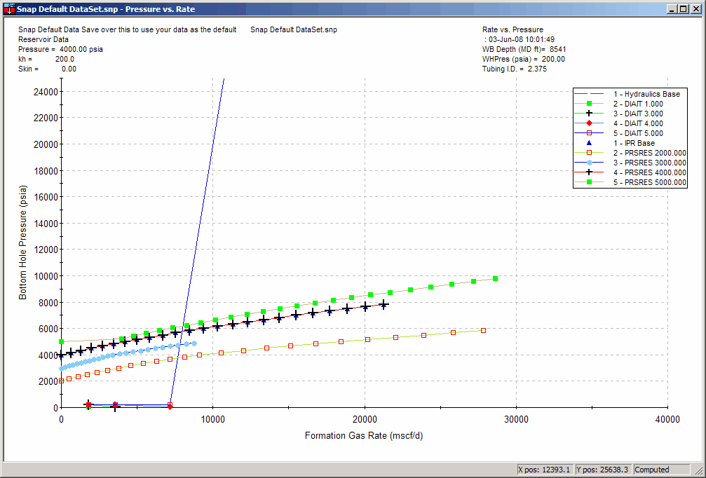
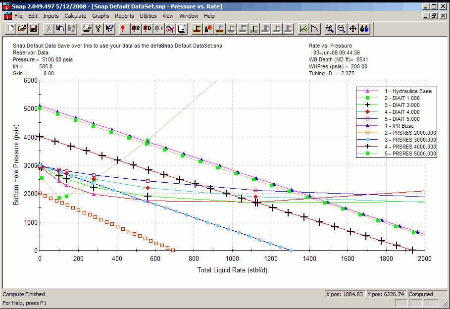
Water injection wells can be modeled by estimating reservoir injection performance, then merging those results with wellbore hydraulics. Results appear “backward” relative to typical nodal analysis: the hydraulics curve moves downward from right to left, and the IPR curve goes up from right to left. Their intersection is still the actual operating rate.
4.4. Gas Injector Wells
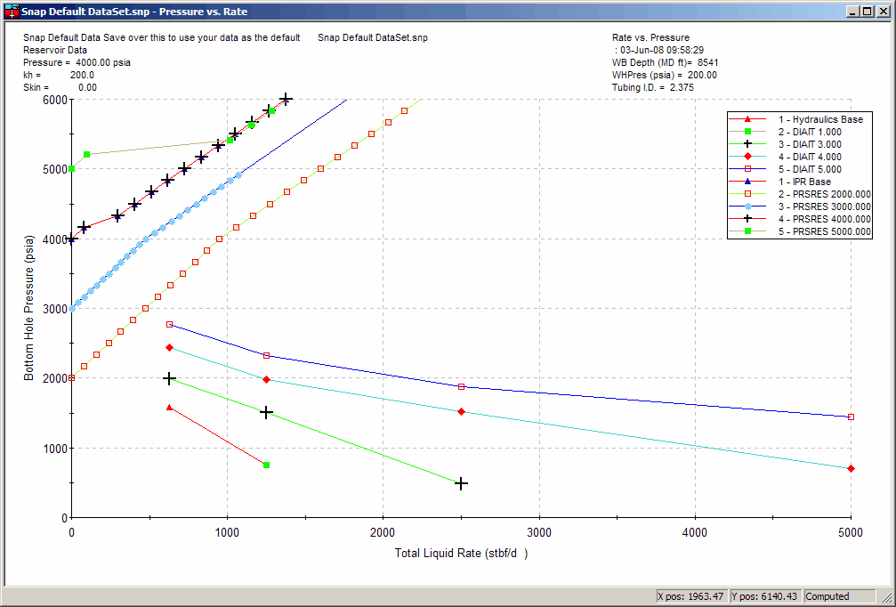
Gas injection wells are modeled similarly to water injectors: estimate reservoir injection performance and merge with wellbore hydraulics. Curves appear reversed relative to typical production nodal plots, and the intersection gives the operating rate.