Artificial Lift Options
The following options are available under Artificial Lift:
-
Simple Point-of-Injection Gas Lift (Beginner)
-
Detailed Gas Lift Design including valve set-up (Intermediate)
-
Gas Lift Surveillance Dashboard (Experts Only)
-
Gas Lift Design Dashboard (Experts Only)
-
Jet Pump design and analysis
-
Plunger Lift analysis (under Construction)
1. Simple Gaslift Modelling
Select Gas Lift in the General Information panel to calculate using gas-lift properties. To include valve effects on a gas-lifted well, also select Gas Lift Design.
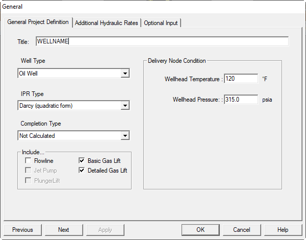
Panels you may see
- Gas Lift Properties appears when Gas Lift is selected.
- Gas Lift Design appears when Gas Lift Design is selected.
- You can also use the expert GasLift Design Dashboard.
- If you selected Gas Lift Valve Design, enter valve data in the Gas Lift Valve Design panel.
1.1. Gas Lift
Editable on the General Gaslift Properties panel
- Measured depth of gas injection (ft): Measured depth of the operating valve. The model assumes sufficient pressure to inject the desired rate at this depth.
- Surface injection pressure (psia): Gas-lift injection pressure at the surface. For the specified injection point, the program computes the required surface pressure and compares it to the specified injection pressure.
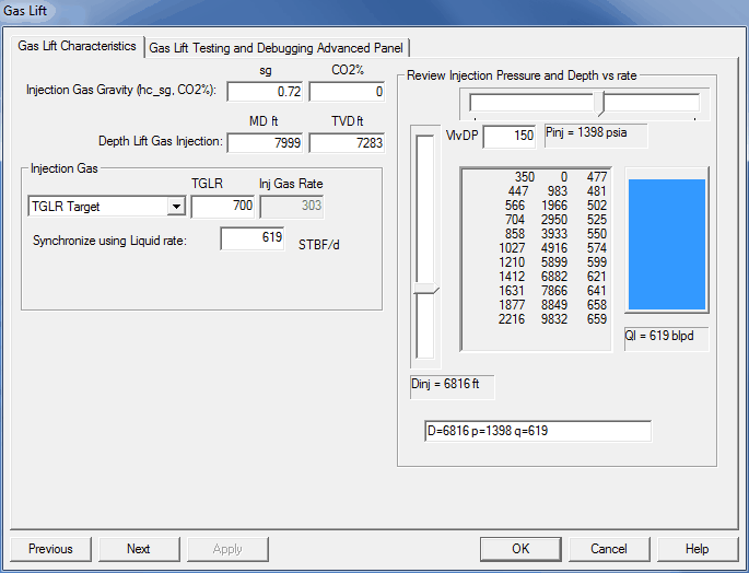
Injection gas volume options
- Gas–liquid ratio (scf/bbl): Ratio of total gas volume (lift gas plus formation gas) to total produced liquid volume.
- Injection gas rate (Mscf/d): Rate of lift-gas injection.
Injection pressure, depth, and resulting rate utility
- Use the controls on the right to test injection depth versus surface injection pressure and predicted flow rates.
- Example shown: depth of injection at 6816 ft results in a GL injection pressure of 1398 psia and a production rate of 619 bbl/d.
- When you first select one of the controls, the program runs a series of cases to determine required pressure at different depths and the associated rates. The blue bar fills as higher rates are obtained.
- This utility helps select target injection depth and injection pressure. If you do not need to study these parameters, you can ignore these controls.
Advanced options are available for testing specific models and experimental technology.
The more complex Gas Lift Design panel requires additional data.
2. Gas Lift Design
Tutorial
For a step-by-step walkthrough, see the Gas Lift Valve Design Tutorial.
Overview
- This panel is a compact dashboard for detailed gas-lift design used by practicing engineers.
- If you are new to this page, the example dataset “8b Gas lift design.snp” is a good starting point.
- A parameter-by-parameter description is provided on the Detailed Gas-Lift Design Parameters page.
Actions
- Apply — computes the gas-lift design for the current inputs and displays both a graphic and a text report.
- To edit placement, type, size, and other properties of each gas-lift valve, open the Valve Design tab.
- To edit operating conditions, open the Gas Lift Trouble Shooting tab.
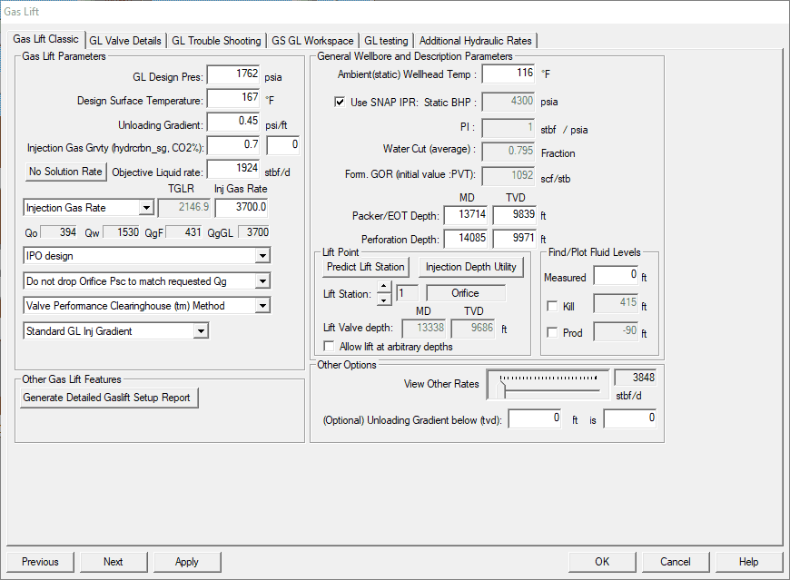
2.1. Detailed Gas Lift Design Parameters
The controls described here are on the Gas Lift Design panel. For a guided walkthrough, see the Gas Lift Valve Design Tutorial.
Gas Lift Parameters: The following items can be edited in the Gas Lift Parameters section:
-
Kickoff GL CSG wellhead pressure (psia): Surface gas-lift injection pressure available during unloading. It should be 30–50 psig less than the maximum maintainable casing pressure at the desired operating rate so that valves actually pass the required gas during unloading.
-
Kickoff wellhead temperature (°F): Tubing temperature during unloading. Often set to the flowing WH temperature. Using a lower temperature for the top one or two unloading valves can help lock them out, but use with caution.
-
Unloading gradient (psi/ft): Heaviest possible fluid gradient. Must be equal to or heavier than the unlifted flowing gradient. A common default is 0.45 psi/ft.
-
Injection gas gravity (sg): Specific gravity of lift gas.
-
Objective liquid rate: Target liquid production rate for the case. The adjacent import button can pull in the rate from a successful hydraulics + IPR run.
Injection gas target options:
-
TGLR target: Target total gas-liquid ratio including formation and lift gas. Linked with Injection Gas Rate Target so changing one updates the other. Enables TGLR sensitivities.
-
Injection gas rate target (mscfpd): Target lift-gas injection rate. Linked with TGLR target. Enables injection-rate sensitivities.
GLR or CALC GLR options:
-
Enter GLR for each valve as the well kicks off: Uses GLR values entered on the Valve Design panel at each unloading station. Recommended. The Gas Lift Simulator Utility can help select GLR.
-
Calc GLR from predicted hydraulic curves: Not recommended in this version. It is not fully implemented and can be inaccurate.
Surface casing pressure options:
-
Drop Psc at orifice to match requested Qg: Decreases surface casing pressure until the calculated gas through the operating valve matches the required lift-gas rate. If matched, an operating casing-pressure line is drawn on the GL plot.
-
Do not drop orifice Psc to match requested Qg: Decreases casing pressure only enough to close unloading valves. Shows the maximum orifice-valve passage without reopening upper valves. No operating casing-pressure line is drawn.
Gas passage method options:
Results from all methods are shown in the gas-lift report after a design run. Performance plots are available on the valve detail panel.
-
Valve Performance Clearinghouse (VPC): Recommended if you have access. Covers throttling and orifice regimes with performance curves for most valves in service.
-
TUALP: Recommended. Covers throttling and orifice regimes based on Tulsa University flow-lab tests. Verify that your valve model was tested.
-
McBride: For 1.5 in OD valves only. Based on field observations.
-
Thornhill Craver: Standard square-edged orifice model used when more rigorous methods are unavailable.
Casing gradient options:
-
Standard or Rigorous: Compute annular lift-gas gradient vs TVD. Rigorous is recommended if compute time is acceptable.
-
Prudhoe: Special method for Prudhoe Bay gas composition. Do not use elsewhere.
Reports and data import:
-
Generate setup report: Produces an RTF document with shop calibration data for the GL valves.
-
Import prior data: Updates the inputs from previous panels. You can also edit any field directly.
Operating conditions and reservoir inputs:
-
Flowing wellhead temperature (°F): Tubing temperature at surface at objective conditions.
-
Static bottom-hole temperature (°F): Temperature at mid-perforation depth.
-
Static bottom-hole pressure (psia): Average reservoir pressure at mid-perforation depth.
-
SNAP IPR or fixed PI: Check SNAP IPR to use previously built inflow. Leave unchecked to enter a fixed PI.
-
Water cut (fraction): Producing water cut for the case.
-
Formation GOR (scf/stb): Produced formation gas only, not including lift gas.
-
Perforation depth (ft): Mid-perforation depth. MD and TVD are linked and computed from the Wellbore Geometry deviation data.
-
Lift depth (ft): Injection depth for the case. MD and TVD are linked and synchronized with the Valve Design depths. The plus or minus buttons step to the next valve depth, skipping dummy valves.
-
Create set-up report: Creates a field procedure and documentation report. Use Open Setup Report to view.
Slick Line Procedure:
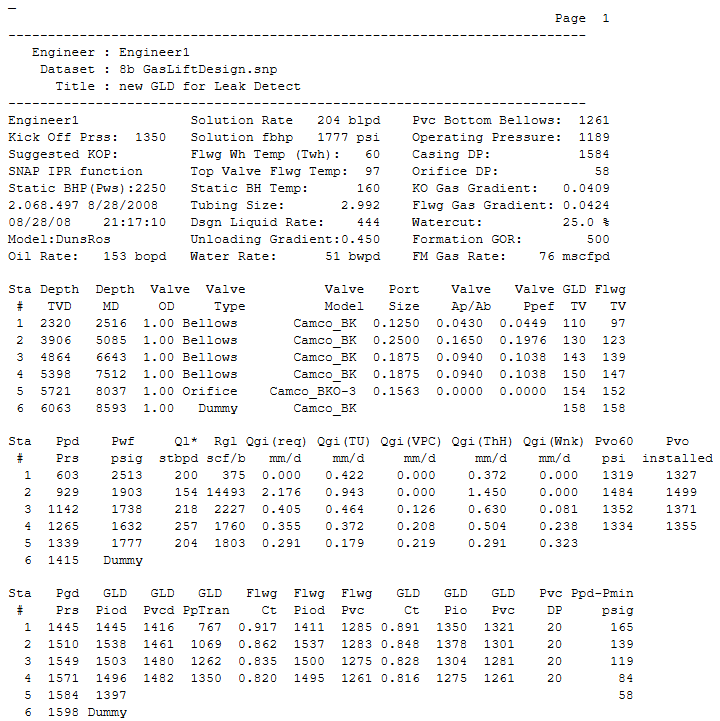
Run the following gas lift design based on the DunsRos hydraulic correlation, at 444.0 BLPD, a kickoff pressure of 1350.0 psi, and Camco_BK valves.
| GLM | MD (RKB) | Valve Size | Valve Name | Port Size | Surf. Open Press | Surf. Close Press | TRO Press 60° F |
|---|---|---|---|---|---|---|---|
| 1 | 2516 | 1" | Camco_BK | 1/8" | 1350 | 1321 | 1319 |
| 2 | 5085 | 1" | Camco_BK | 1/4" | 1378 | 1301 | 1484 |
| 3 | 6643 | 1" | Camco_BK | 3/16" | 1304 | 1281 | 1352 |
| 4 | 7512 | 1" | Camco_BK | 3/16" | 1275 | 1261 | 1334 |
| 5 | 8037 | 1" | Camco_BKO-3 | 5/32" | ------ Orifice ------ | ||
| 6 | 8593 | 1" | Camco_BK | ------ Dummy ------ | |||
Recommended Unloading Procedure:
- Slowly open the production choke to reduce tubing pressure to common line pressure.
- Start lift-gas injection at 50–150 Mscfd.
- Monitor casing-annulus pressure and target 50–100 psi increase every 30 minutes.
- Increase lift-gas injection to a maximum of 200 Mscfd.
- At 200 Mscfd, the time to drop the annulus fluid level to the first GL valve is 5.3 hours.
- After reaching the first valve, increase the lift-gas rate to two-thirds of the design rate. Example: .
- The annulus level will pass each unloading valve and stabilize injection at the orifice within 12–18 hours depending on valve count.
- Confirm annulus casing pressure is below the closing pressure of the bottom GL valve, for example 1297 psig.
- Increase the lift-gas rate to the design rate, for example 533 Mscfd.
- Expected stabilized operating annulus casing pressure, for example 1554 psig.
- Contact the production engineer or artificial-lift team for any issues unloading the well, or if operating annulus casing pressure deviates by ±150 psi from design.
2.2. Gas Lift Valve Design
Tutorial
For a guided walkthrough, see the Gas Lift Valve Design Tutorial.
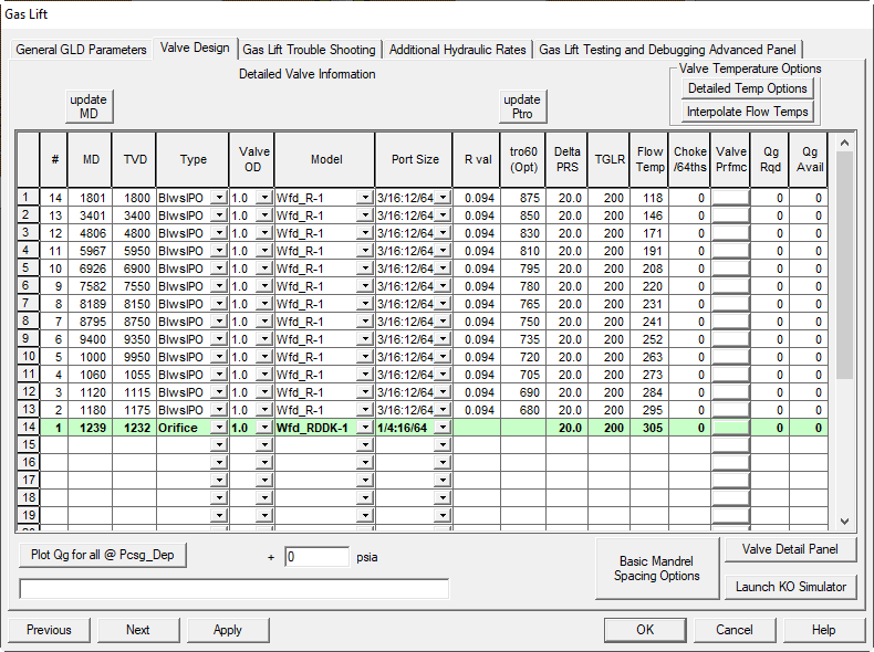
Editable fields on the VALVE DESIGN panel
-
TVD and MD (ft)
True vertical depth and measured depth of each mandrel. If TVD is edited, click UPDATE MD to back-calculate MD from Wellbore Geometry. -
VALVE TYPE
Choose Bellows, Orifice, or Dummy. The top row must be Bellows or Orifice. Remove Dummy rows above the first live valve. -
MANUFACTURER
Select from the list. If your make is missing, use Camco. -
VALVE OD
Pick 1 in or 1-1/2 in outside diameter. -
PORT SIZE
Available diameters range from 1/8 in to 3/4 in depending on valve make and size. Adjust ports so the operating valve can pass the required lift gas. For the top valve use the smallest port that still meets the rate to conserve casing pressure. -
R VALUE (Av/Ab)
Ratio of port area to bellows area. Auto-filled when valve parameters are valid. You may override with vendor values. Note that custom R values can affect TUALP behavior. -
TRO60 (psig)
Test Rack Opening pressure at 60 °F. After running Apply, click UPDATE TRO to load calculated TROs. For troubleshooting runs, type the actual installed TROs. -
DELTA PRESSURE (psig)
Controls the surface closing pressure step-down from one unloading valve to the next. Sum of all deltas is subtracted from the top-valve surface closing pressure to compute maximum surface casing pressure. Use sufficient deltas to avoid valve interference. Designers often scale deltas with supply pressure, for example 10 psig at 800 psig systems, 20 psig at 1400 psig, 50 psig at 1800 psig. -
GLR (TGLR)
Total gas liquid ratio required to transfer lift from the current unloading valve to the next. Use the Gas Lift Simulator Utility to help define. Target tubing pressure at the current depth must be less than or equal to the transfer pressure defined by the intersection of the unloading gradient and the current depth line. -
FLOWING TEMPERATURE (°F)
Tubing flowing temperature at valve depth under objective conditions. Used in troubleshooting. Click interpolate to straight-line interpolate from surface flowing temperature. Replace with survey data if available. -
STATIC TEMPERATURE (°F)
Used for TRO calculations in this program version. Click interpolate to straight-line interpolate from the kickoff wellhead temperature. Replace with survey data if available. -
USE
Reserved for future selection of which temperature column to use for TRO. Current version uses STATIC TEMPERATURE.
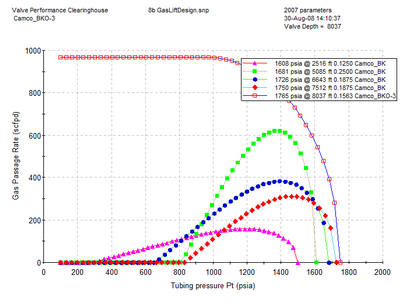
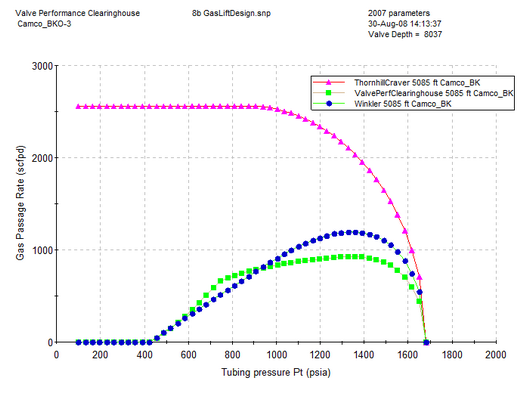
Plot Qg for all methods
Click Plot Qg for all methods to create or update performance plots for the selected valve at the specified casing pressure over a range of tubing pressures. Results from all methods are shown on the gas lift report. You can also access per-valve performance plots on the valve detail page.
Thornhill Craver Method:
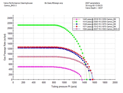
VPC Method:
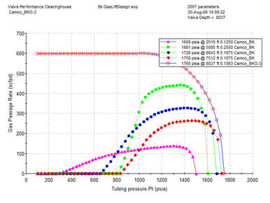
Winkler Method:
Single-valve testing:
Select one valve, press Plot, and test alternate reservoir pressures to compare methods for that specific valve.
2.2.1. Detailed Temperature Options for Gas Lift
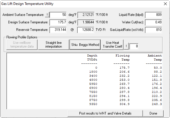
This expert panel is used to model and predict flowing wellbore temperatures.
Available methods
- Straight-line interpolation: simplest approach.
- Shiu-Beggs method: empirical, matches measured data well and can be tuned to known temperature profiles.
- Rigorous heat transfer: most detailed method.
Tuning the Shiu-Beggs method
- Enter a known temperature profile on the actual-data panel.
- Create a first-pass Gas Lift plot using the conditions that were valid when the survey was run.
- With the temperature options panel open, adjust the ambient temperature, press Shiu-Beggs Method, then press Post results...
- Repeat adjustments and posting until the error between the measured and predicted profiles is minimized.
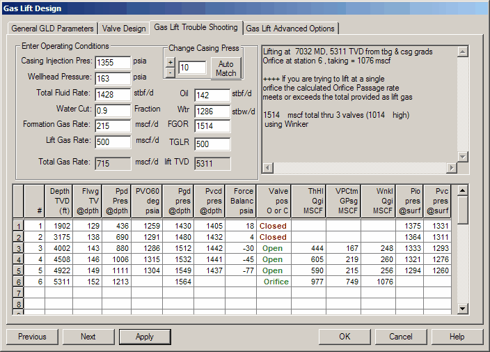
2.3. Gas Lift Design Trouble Shooting
This panel lets you test an existing gas-lift design and predict performance of valve placements and settings. It applies whatever values are in the input cells. It is useful for checking whether the design gas volume can pass through the last valve or if multi-point lifting is likely. Output cells are locked and update only when you change inputs here or on prior panels.
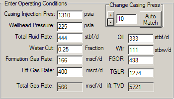
Editable items on the Trouble Shooting panel
-
Casing Injection Pressure (psig): Surface casing pressure under operating conditions. The starting value is imported. Click AUTO MATCH to compute a matching casing pressure for the current case. To run a what-if, type a new value and click APPLY to update the outputs.
-
Wellhead Pressure (psia): Flowing tubing pressure at surface. Imported initially. Change it and click APPLY to re-solve. You can also use the + / − Change Casing Press buttons. Default increment is 10 psig, but you can override it.
-
Total Fluid Rate (blpd): Total liquid rate. Linked to Water Cut, Formation Gas Rate, Oil, Water, FGOR, and TGLR. Editing this will automatically update the others. Click APPLY to re-solve.
-
Water Cut (decimal fraction): Linked to Formation Gas Rate, Oil, Water, FGOR, and TGLR. Edit, then APPLY to update the outputs.
-
Formation Gas Rate (mscfpd): Formation gas volume for the case liquid rate and FGOR. Linked to Water Cut, Oil, Water, FGOR, and TGLR. Edit, then APPLY.
-
Lift Gas Rate (mscfpd): Injected lift-gas rate. Linked to TGLR so updating either will update the other. Edit, then APPLY.
-
Oil (bpd): Produced oil rate. Linked to Total Fluid Rate, Water Cut, Formation Gas Rate, Water, FGOR, and TGLR. Edit, then APPLY.
-
Wtr (bpd): Produced water rate. Linked to Total Fluid Rate, Water Cut, Formation Gas Rate, Oil, FGOR, and TGLR. Edit, then APPLY.
-
FGOR (scf/stb): Linked to Total Fluid Rate, Water Cut, Formation Gas Rate, Oil, Water, and TGLR. Edit, then APPLY.
-
TGLR (scf/stb): Total gas liquid ratio including formation and lift gas. Linked to Total Fluid Rate, Water Cut, Formation Gas Rate, Oil, Water, and FGOR. Edit, then APPLY.
2.3.1. Trouble Shooting Grid Description
GLTS compares the tubing pressure gradient with the operating casing injection pressure to determine:
- If the lift point is at the orifice and the volume of lift gas that will pass through the orifice.
- If unloading valves are open or closed and the lift-gas volume through each valve.
- Depth TVD (ft): Gas-lift mandrel set depth, ft TVD.
- Flwg TV @ depth: Flowing temperature of produced fluid at depth, based on surface FTT and either the Shiu or interpolation method.
- Ppd Pres @ depth: Flowing production pressure in tubing at depth, based on surface FTP, hydraulics correlation, wellbore geometry, PVT, flow rate, and lift-gas rate.
- PVO 60 deg psia: Test rack opening pressure of the installed gas-lift valves.
- Pgd pres @ depth: Casing pressure opposite the valve and mandrel at the given conditions.
- Pvcd pres @ depth: Dome pressure at depth where the valve is closed, based on Flwg TV and PVO 60.
- Force Balance (psia): Describes how open or closed a valve is:
- Difference between operating casing injection pressure at surface and the surface closing pressure Pvc of the valve.
- Negative means valve is open. Positive means closed. Small magnitude means the valve is near its threshold.
- Valve Pos Open or Closed: Displays Closed in red when closed and open in green when open.
- ThHl Qgi (MSCF): Gas passage rate predicted by the Thornhill Craver method at that valve location.
- VPCtm Qgi (MSCF): Gas passage rate predicted by the Valve Performance Clearinghouse method.
- Wnkl Qgi (MSCF): Gas passage rate predicted by the Winkler method.
- Pio pres @ surf: Surface casing pressure to open the valve, based on pressure to open at depth (Piod) minus lift-gas column weight.
- Pvc pres @ surf: Surface casing pressure to close the valve, based on closed dome pressure at depth (Pvcd) minus lift-gas column weight.
2.4. Gas Lift Design Advanced Options
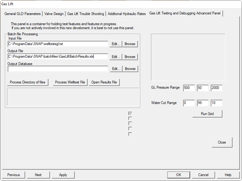
Gas lift advanced options are undocumented specialty utilities and should not be used unless you are working with the program developers on specific needs. Contact the program contacts if you require these or other specialty utilities.
When to use this panel
Use only for developer assisted studies, prototyping, or diagnostics that are not supported in the standard workflow. Changes here can materially affect calculations and visualizations elsewhere in the Gas Lift Design module.
3. Gas Lift Surveillance Dashboard
3.1. Dashboard View
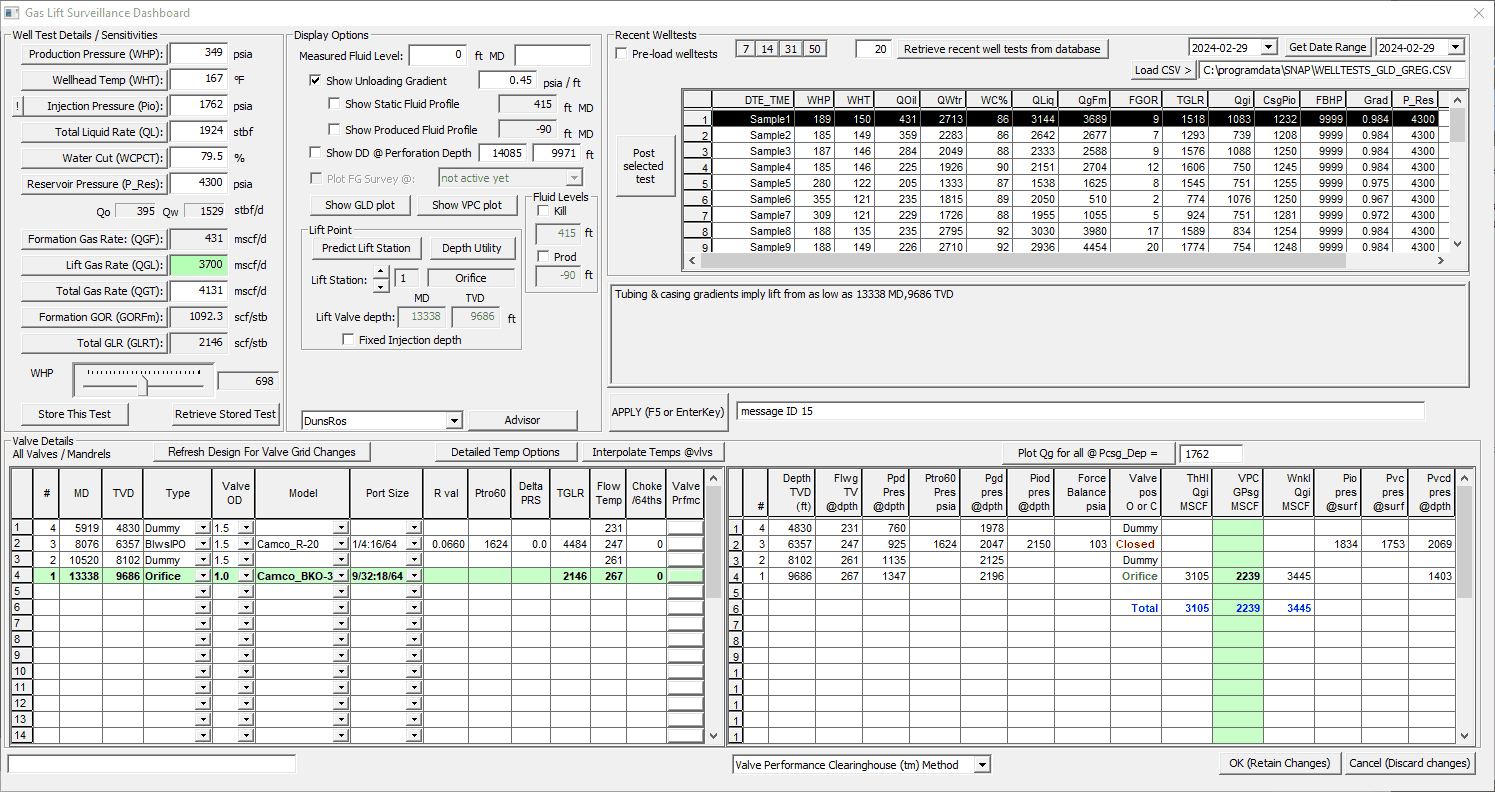
The Gas Lift Surveillance Dashboard provides an interactive workspace for analyzing recent well tests and running what-if scenarios. It is large and most effective on two screens.
Typical workflow:
- Load a set of recent well tests into the upper-right grid from an integrated database or a
.csvimport. Copy-and-paste from other programs also works. - Select a row and click Post selected test to push that well test to the model. Plots and reports update automatically.
- Adjust any value on the left panel to test conditions. You have four ways to change a value:
- Type a new number then press Enter, F5, or the APPLY button.
- Select the item then move the slider at the bottom of the group.
- Select the item then use the mouse wheel.
- Select the item then use the keyboard arrow keys.
Grids and valve views:
- The lower-left grid lists all valves. The current lift station is highlighted in light green.
- The right-side grid lists all live valves. The selected gas-passage method is highlighted in green.
- To view valve performance curves for a specific valve, click the Valve Prfmc. button on that row.
- To generate performance curves for arbitrary injection pressure at depth (plus extra pressure), use Plot Qg for... in the lower-right area.
Usage guidance
This panel is an interactive dashboard without a fixed data-entry order. It is intended as a what-if simulator for experienced gas-lift surveillance engineers.
4. Jet Pump Options
The following are Jet Pump topics with help available:
-
Jet Pump Input Panel
-
Panel Data Items
-
Jet Pump Design Basics
4.1. Jet Pump Input Panel
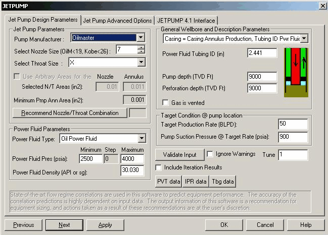
SNAP models the performance of a jet-pumped well using techniques developed over many years. Jet-pump design is complex and typically not covered in standard petroleum engineering curricula. In practice, designing jet-pumped wells is treated as an art that requires experience to consistently achieve expected performance. These input panels are intended for experienced jet-pump modelers and are aligned with manufacturer workflows.
Assumptions and scope
- Users are familiar with hydraulic pumping concepts, jet-pump operation, and the size designations used for jet pumps.
- If you are new to these topics, see the Jet-Pump Primer section in this help.
- Input is interactive and menu-driven. Data validity checks are included, and defaults exist for some variables.
Recommended references
- Hal Petrie, Phil Wilson, Eddie Smart, “Jet Pumping Oil Wells,” World Oil, Nov 1983, Dec 1983, Jan 1984.
(Equations in that series were intended for handheld calculators rather than computers.) - Petroleum Engineering Handbook, Society of Petroleum Engineers, Chapter 6 on hydraulic pumping
(basis for the algorithms used in SNAP jet-pump design).
4.2 Jet Pump Panel Data Items
Jet Pump Parameters:
- Pump Manufacturer: Enter the type of pump used.
- Nozzle Size (Oilmaster < 19, Kobe < 26): Enter the nozzle size for the selected pump.
- Throat Size: Letters Y, X, A, B, C, D, E, F indicate available flow area for produced fluids. As sizes are selected, the annulus area cell updates with the current size in in².
- Recommend Nozzle/Throat Combination: Reviews inputs and suggests a combination based on standard design relationships. Treat this as guidance only.
Power Fluid Parameters:
- Power Fluid Type: Oil or Water: Select the power fluid type. Default is oil.
- Power Fluid Pressure Range: Four power-fluid pressures are run to determine the performance range. Enter a value in Minimum or Maximum to auto-update the step value when another cell is selected.
- Power Fluid API or Specific Gravity: Enter API gravity if oil is the power fluid, or specific gravity if water. The power fluid SG may differ from the produced oil or water SG.
General Wellbore and Description Parameters:
- Pump Installation Type: Choose Parallel, Casing, or Reverse. The image updates to reflect the flow configuration.
Parallel Free System:
![]()
The system uses one tubing string to conduct power fluid down to the pump and BHA (downstring) and a separate, parallel tubing string to return produced fluids and spent power fluid (upstring).
Casing Free System:
![]()
One tubing string supplies power fluid (downstring). Produced fluids and spent power fluid return up the casing–tubing annulus.
Concentric installations are modeled with the casing-free option by setting a smaller tubing inside a larger tubing. Input the larger tubing ID as the casing ID. Other inputs (except surface producing GOR) are as in the standard casing-free evaluation. The GOR value depends on the installation design and the effectiveness of any venting system.
Reverse Flow System:
![]()
Power fluid goes down the casing–tubing annulus or a separate power-fluid supply tubing (downstring). Produced fluids and spent power fluid return up a tubing string (upstring).
Description Information:
Description fields adjust based on the selected configuration. Remaining physical description items are entered on the following Wellbore panel. Depending on selection, some items may not be shown or required.
- Power Fluid Tubing ID (in): Enter the actual ID for the power-fluid tubing. Return-path values are defined on the Wellbore panel. For reverse-flow systems, see the installation-type notes above regarding tubing diameters.
- Casing ID (in): Enter the actual internal diameter through which fluid flows. Scale, paraffin, or iron sulfide can reduce the effective ID relative to the steel size.
- Upstring Tubing ID (in): Enter the actual ID for the return fluids. Use the hydraulic diameter, not drift diameter. This appears when the parallel-free option is specified.
In three-string BHAs, the jet may return fluid up both return strings. Determine an equivalent upstring ID that yields the same friction drop as the two return strings combined. - Downstring Tubing OD (in): Enter the actual tubing OD, not the coupling OD. Not shown for the parallel-free option. Always associated with the power-fluid supply tubing.
- Pump Vertical Depth (ft): True vertical depth to the end of the pump BHA. If different from perforation depth, the pump intake pressure is corrected from FBHP at perforations to the pump set depth using true flowing conditions.
- Perforation Depth (ft): TVD to the midpoint of the perforation interval(s). FBHP is assumed at this midpoint.
- Gas is vented (checkbox): Check if gas bypasses the pump via capillary or other means. This controls whether the program estimates gas vent volumes in performance calculations. Default is unvented.
![]()
![]()
![]()
Parallel Reverse Casing
Notes on downhole gas vents: If vented, the program computes free gas at each pump intake pressure, multiplies by the area ratio of power-fluid string ID to casing ID, and assumes that portion goes through the pump with the remainder vented. Typical installations vent about 80 percent of free gas with this method. Concentric installations may be underestimated because the ratio uses two tubing strings rather than tubing to casing. Consider venting if GOR is high or pump intake pressure is low. Venting can improve pump performance but may raise pump discharge pressure due to less gas in the return conduit. Net effect depends on the balance of these factors.
Well Test Parameters:
- Target Well Test Flow Rate (BLPD): Enter total liquid rate (oil and water) as a 24-hour rate. If tests were not 24-hour, estimate the equivalent 24-hour rate since correlations are based on daily volumes. Rate and FBHP lie on the IPR; setting one updates the other.
- Target Pump Suction Pressure @ Well Flowing BHP (psig): Enter the steady-state FBHP corresponding to the specified total liquid rate. Accuracy of the IPR-based response depends on accurate rates and pressures.
4.3 Jet Pump Advanced Options
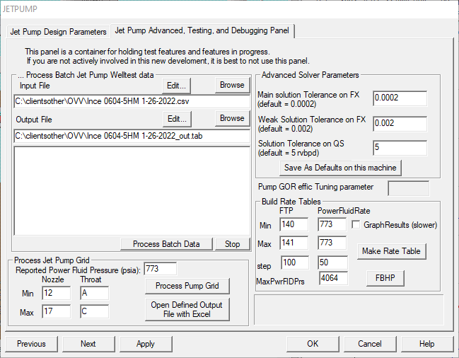
Jet pump advanced options are undocumented specialty utilities intended for use with guidance from the program developers.
When to use
Only use these advanced options when you are collaborating with the developers on a specific need or diagnostic study.