Gas Lift Valve Design Tutorial
1. Objective
Determine optimal gas-injection volume and depth, space mandrels, and size valve ports.
Gas Lift Valve Ordering and Behavior
The gas lift valves are ordered by descending measured depth with valve number. The deepest valve is valve #1, the second deepest is #2, and so on. If Last Valve Always Open is ticked, then PSC and PSO for valve 1 (if specified) will be disregarded by the calculator.
2. Getting Started
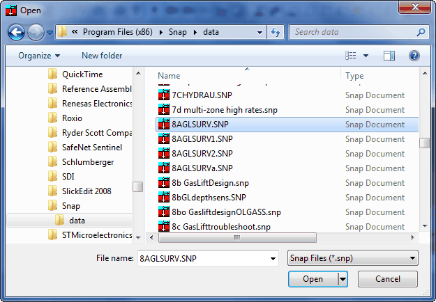
- Open SNAP → File → Open, then open the example file:
C:\Program Files (x86)\SNAP\8aGLSURV.snp. - Page through each panel to familiarize yourself with the raw input data.
- Run the case and review the results.
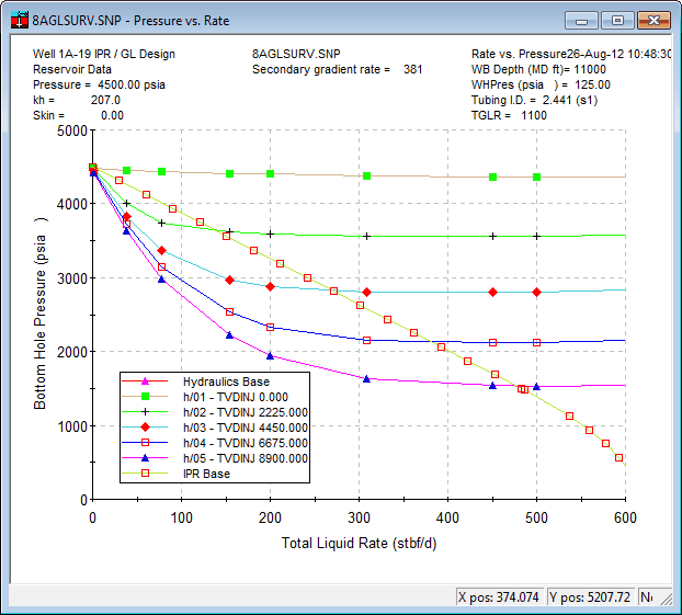
3. Choose Injection Depth
The depth sensitivity implies “the deeper the better.” Go to the Gas Lift panel and place the injection point as low as physically possible (start with 8900 ft TVD).
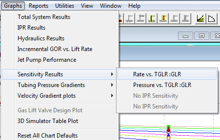
4. Run a GLR Sensitivity
After confirming that lower injection depth is better, go to Sensitivities and run a sensitivity on Gas Lift GLR.
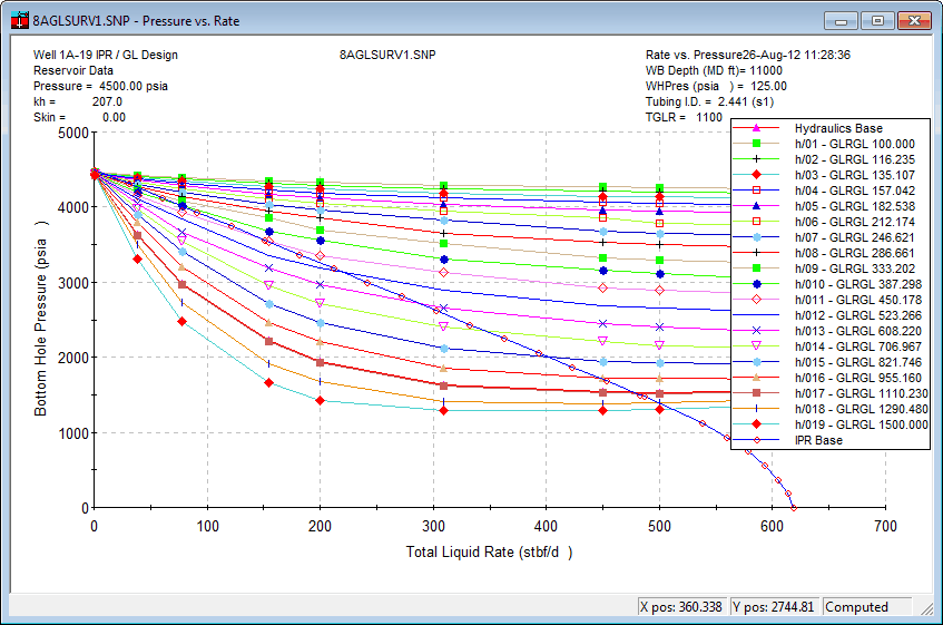
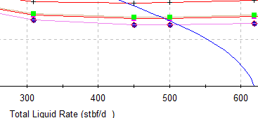
What you see indicates significant variance in lift with GLR, so plot the sensitivity graph:
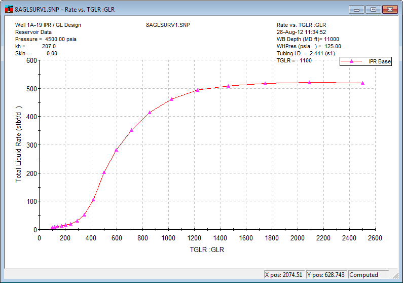
5. Interpret the Sensitivity
The well only needs about 1200 GLR before it starts overlifting (oil rate no longer increases with GLR). Use ~1200 GLR as a starting point for detailed design.

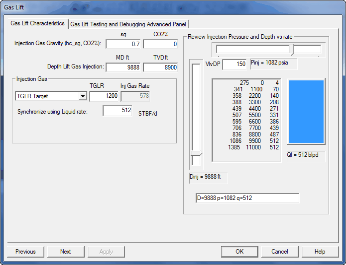
6. Estimate Design Targets
On the Gas Lift Design page you can estimate potential liquid rate and required injection pressure.
For this case, design for TVD 8900 ft, operating injection pressure > 1080 psia, and liquid rate 500 BLPD.
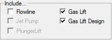
7. Switch to Gas-Lift Design Mode
Return to the General tab and check Gas Lift Design.
Page forward (Next) until you reach the Gas Lift Design page.
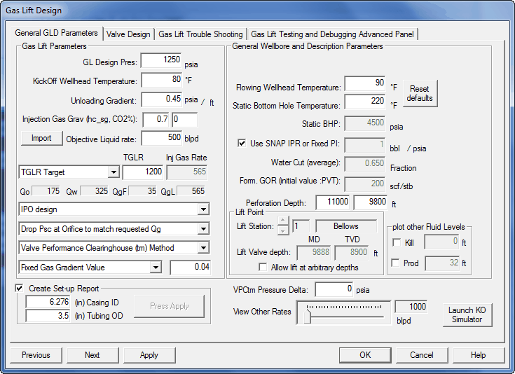
8. Enter Initial Design Parameters
Enter your best estimates. The Kick-off pressure should be well above the ~1082 psia operating pressure to allow step-down through the valves. Enter 500 BLPD, or click Import near the objective Liquid Rate to pull it from the prior solution.
The nodal plot indicates the well can produce 500 BLPD, but your lift system must have sufficient lift pressure and gas rate to match the design.
9. Set Default Injection Depth and Apply
If the default injection depth is not at the design lift point, adjust the single default valve to that depth (e.g., 8900 ft).
Press Apply to see the case without detailed valve data.
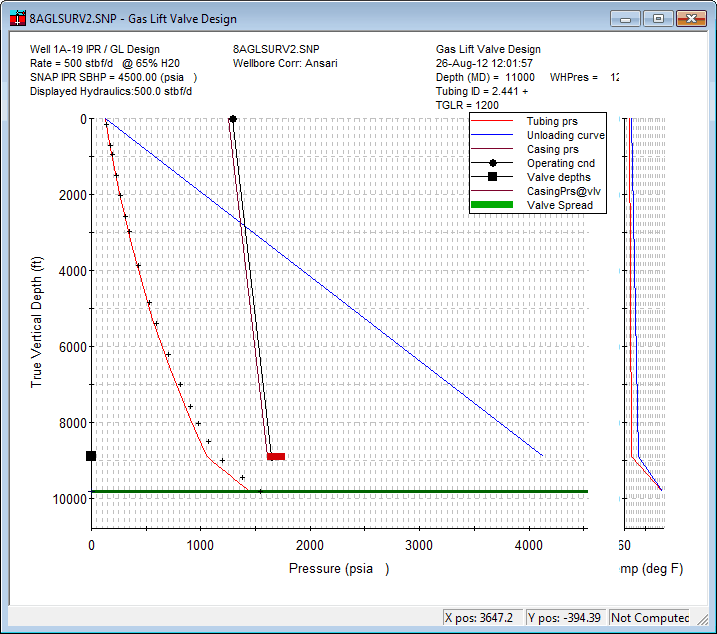
You have sufficient lift-gas volume and pressure to lift to the design depth. Assume 1250 psia available for now (higher pressures lift greater volumes but may not require unloading valves).
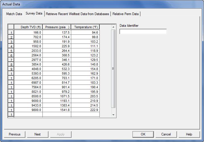
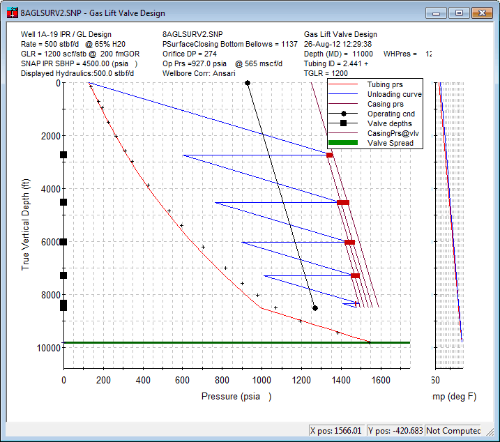
Survey “crosses” on the gradient plot help check hydraulics at the survey conditions. A kink near 8900 ft suggests lifting at that location. After changing rate/GLR/depth, do not expect the survey to match.
Save the dataset under a new name for valve design work.
10. Mandrel Spacing Utility
Re-open the Gas Lift panel → Valve Design tab. You’ll see one default valve at 8900 ft (it will be discarded when spacing is computed). Click Mandrel Spacing Utility.

Set preferences (max injection depth, design options).
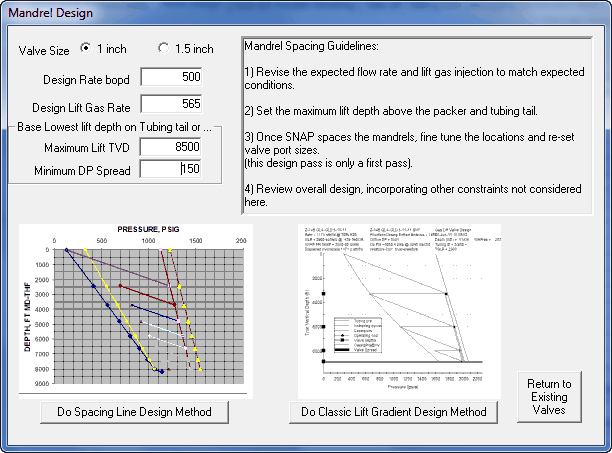
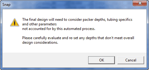
When you click Do Spacing Line Design Method, you’ll be reminded the design is approximate and must be independently reviewed for accuracy and suitability.
The program generates spacing (about 6 valves typical) based on your inputs and local preferences. Slight differences from the screenshots are expected.
11. Post Test-Rack Pressures and Update
Before reviewing the design plot, post the design Test-rack pressures to the case and Apply.
BEFORE pressing “Update PVO”:
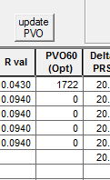
AFTER pressing:
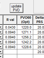
The design plot now shows the operating pressure (e.g., 927 psia) in the header.
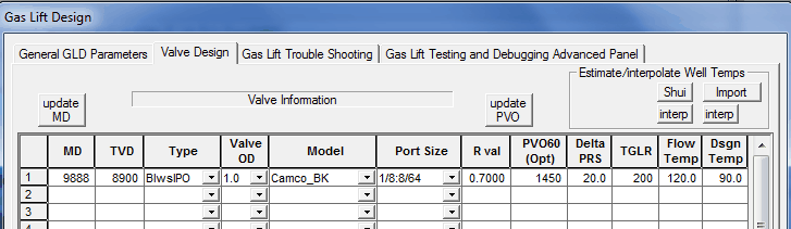
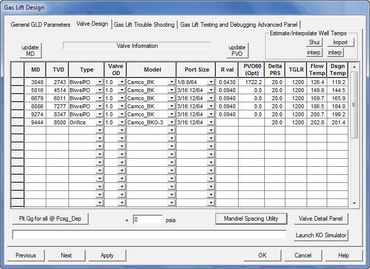
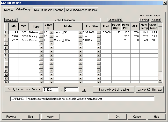
12. Finalize Valve and Port Details
Return to the Valve Design tab and adjust to the actual valves you plan to purchase.
Adjust port sizes so the Gas-lift report shows each valve passing the required gas at its location. For this case, you may need 1.5" mandrels to pass sufficient gas at the required rates/volumes.
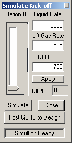
1) Use the Gas-lift Kick-off simulator to tune required lift-gas rates at each valve and determine needed port sizes.
2) Ensure the black operating condition line appears on the plot so you can confirm the orifice is passing the design amount.
3) Add extra mandrels for unanticipated conditions and test scenarios. Dummy off unneeded mandrels. Click Interpolate Temps and Update MD to align with correct gyro locations.
13. Known Limitations in This Simple Design
1) It is not possible to move enough gas through the top valve to reach the second location with a 1" mandrel.
2) The orifice already uses the largest port, so there is no option to up-size.
This technology is best applied by experienced designers, but this short tutorial demonstrates the inputs and decisions involved in a typical valve-design workflow.